P1 wireless kinetic switch specification
1. product overview
1.1 Product introduction
P1 wireless kinetic switch is a self-powered switch, built-in energy acquisition module, which converts mechanical energy pressed by finger into electrical energy, activating the wireless signal transmission. P1 features wireless on/off and dimming control, equipped with Ebelong wireless receiver for controlling.
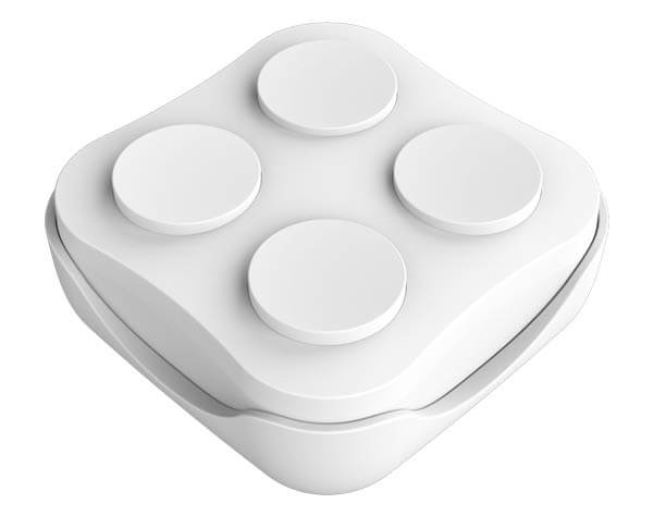
1.2 Product pictures

2. Function and features
2.1 Pair with Ebelong wireless receiving controller
A. General pairing:
P1 series of switches function with wireless receiving controller, the pairing method is: long press on “pairing” button of receiver for three seconds, when indicator flashes slowly, press any buttons from P1 to get both units paired (Be sure not to press too much shorlty). Indicator goes off that means pair succeeds. Now P1 can be used to control receiver (for the function of receiver, please refer to the manual related to the wireless receiving controller).
B. Directed pairing
To enable products working compatible with users’ traditional habits, the Directed pairing helps to make sure one switch controls more than one receiving controllers at the same time.The pairing method is: long press “pairing” button on receiver for three seconds, loose your finger from the button when its indicator flashes, press any key from P1 for 4 times within 1 second, indicator goes off that means pariing succeeds. Now Pairing completes.
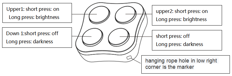
After pairing is finished, it functions as follows:
upper key for turning on, down key for turning off. Long press upper key / down key to adjust dimming up and down. With Directed pairing mode, four keys of P1 are programed at two independent groups, identificated through the hanging rope hole in low right corner. Both upper key and down key are a group, two groups works at same paring program, details is shown as below:
2.2 Installation instructions
P1 switch is available with either handheld way or special bottom case provided (It fixes by magnetic suction, holder base is optional), the holder base can be mounted at two ways: Paste 3M sticker included to the clearn wall or glass surface. Or fix it with screws onto the wall. Installation method:
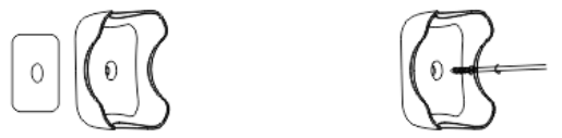
Step1: peel off one side of 3m adhesive Tape mounted on bottom case, stick to the firm clean surface; or fix the bottom case to the wall by screw.
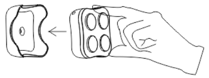
Step2: fix the switch to the bottom case by magnetic suction (PI and bottom case both come with magnet).
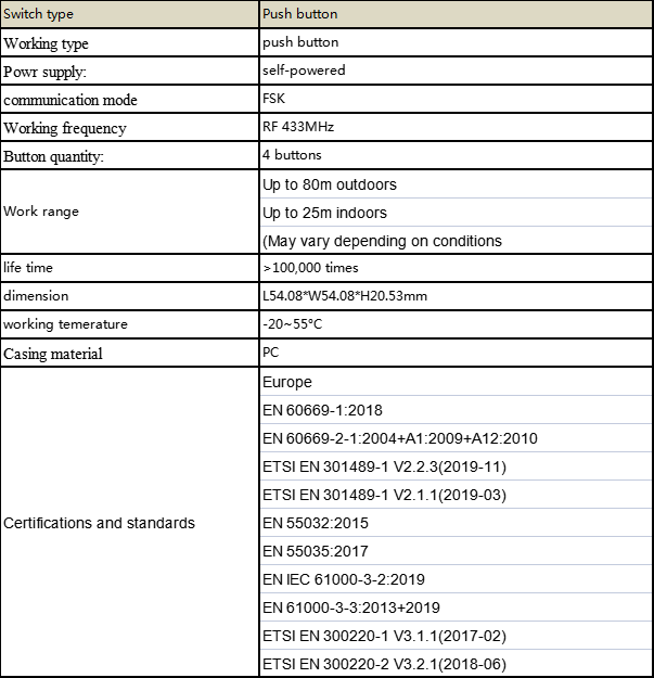
3. Specification
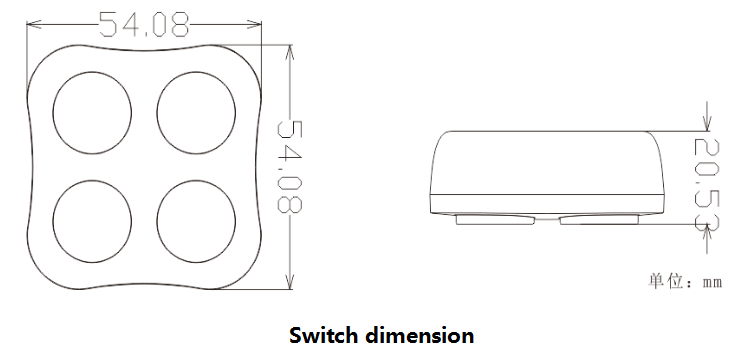
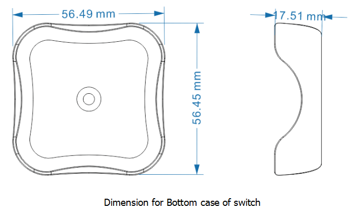
4. Production dimension